Before you actually build anything using this guide, please read the disclaimer.
Input - The Joystick Port
To start off, let's look at the simplest way of attaching an input device to your CPC - the joystick port.
CPC joysticks are essentially just a bunch of switches in a fancy box. Moving the joystick or pressing the fire button closes one or more of the switches. Reading the joystick port using BASIC's JOY command will give different numbers depending on which switches are being pressed at the time.
(Incidentally, if you didn't know, Atari joysticks are compatible with the CPC. I've also heard rumours of Sega Megadrive game pads working on the Amstrad, though I admit I've never tried it)
Joystick Port Pin Diagram

| Pin | Switch | Pin | Switch | Pin | Switch |
|---|---|---|---|---|---|
| 1 | Up | 4 | Right | 7 | Fire 1 |
| 2 | Down | 5 | Spare | 8 | Common |
| 3 | Left | 6 | Fire 2 | 9 | Common 2 |
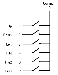
When a joystick switch is pressed, it simply completes a circuit linking one of the direction pins (pins 1 to 4) or a fire pin (pin 6 or 7) to the Common pin (pin 8)
A joystick wiring diagram is pictured below. (Confusingly, on an ordinary joystick, the main fire button is "Fire 2")
 |
| Circuit diagram for joystick 0 |
Joystick 1 works just the same as joystick 0, except that all its switches (pins 1 to 7) link to pin 9 (Common 2) instead of pin 8.
Reading the Joystick
In BASIC:
Easy! Use BASIC's JOY command. This returns a bit-significant value (i.e. when the number is expressed in binary, each digit corresponds to one of the joystick switches) for the joystick number supplied.
The command works as follows:
JOY(n)
Where n is the number of the joystick to be read (an integer expression equalling either 0 or 1).
The command returns a bit-significant value from joystick n:
| Bit | Switch | Decimal value |
|---|---|---|
| 0 | Up | 1 |
| 1 | Down | 2 |
| 2 | Left | 4 |
| 3 | Right | 8 |
| 4 | Fire 2 | 16 |
| 5 | Fire 1 | 32 |
If a bit in the result is set (equal to 1), then that switch is being pressed.
For example, if the main fire button (Fire 2) of the first joystick is pressed while the joystick is being moved right, JOY(0) will return a value of 011000 binary (24 decimal, corresponding to 16 for Fire 2, plus 8 for Right).
Example program:
10 PRINT "Operate the joystick"
20 x=JOY(0):IF x<>0 GOTO 30 ELSE GOTO 20
30 PRINT:PRINT "JOY(0) returned value ";n
40 PRINT "(";BIN$(x,6);" in binary)"
50 END
In Machine Code
This is nearly as easy as in BASIC. Well, if you use the handy firmware call that Amstrad provided for you, anyway. And that's what I'm going to tell you about (if you can write firmware-free code, you probably know how to read the joystick. Even if you don't, you're probably capable of hacking a game to find out how the professionals do it, anyway).
KM GET JOYSTICK: CALL &BB24
| Bit | Switch |
|---|---|
| 0 | Up |
| 1 | Down |
| 2 | Left |
| 3 | Right |
| 4 | Fire 2 |
| 5 | Fire 1 |
| 6 | Spare (usually unconnected) |
| 7 | [Always zero] |
Entry conditions:
None
Exit conditions:
H contains state of joystick 0.L contains state of joystick 1.
A contains state of joystick 0.
Flags corrupt. All other registers preserved.
Notes:
The bytes returned for the joystick states are bit-significant as in the table on the right. If a bit is set then the appropriate button is pressed.
In normal operation the key state map is updated by the key scanning routines every fiftieth of a second, so the states returned may be slightly out of date.
Joystick 1 is indistinguishable from certain keys on the keyboard.
Back to: